
Genesys News
Latest From Genesys


March 09, 2026
Moog’s Genesys GRC 4000 4-Axis Autopilot Receives FAA TSOA
Unlocking Enhanced Capabilities Across Rotorcraft Platforms Mineral Wells, TX – Moog Inc. (NYSE: MOG.A and MOG.B), a worldwide designer, manufacturer, and systems integrator of high-performance precision motion and fluid controls and control systems announced its Genesys GRC 4000 4-axis rotorcraft autopilot has received FAA Technical Standard Order Authorization (TSOA). Moog is actively integrating the new […]
READ MORE
March 03, 2026
Moog’s Genesys GRC 4000 Autopilot Achieves Automated UH-60 Flight
Successfully Demonstrates Auto Liftoff, Hover, Enroute Flight and Landing Mineral Wells, TX – Moog Inc. (NYSE: MOG.A and MOG.B), a worldwide designer, manufacturer, and systems integrator of high-performance precision motion and fluid controls, and control systems announced a milestone demonstration of its Genesys GRC 4000 4-axis rotorcraft autopilot. Integrated into the Black Hawk Genesys […]
READ MORE February 03, 2026
Moog’s Genesys Avionics Suite Takes Flight on ALH
Delivering Advanced Innovation in Record-Breaking Cadence Mineral Wells, TX – Moog Inc. (NYSE: MOG.A and MOG.B), a worldwide designer, manufacturer, and systems integrator of high-performance precision motion and fluid controls, control systems, and avionics announced today a major milestone: the successful first flight of its innovative Genesys Avionics Suite™ aboard Hindustan Aeronautics Limited’s (HAL) […]
READ MORE
July 28, 2025
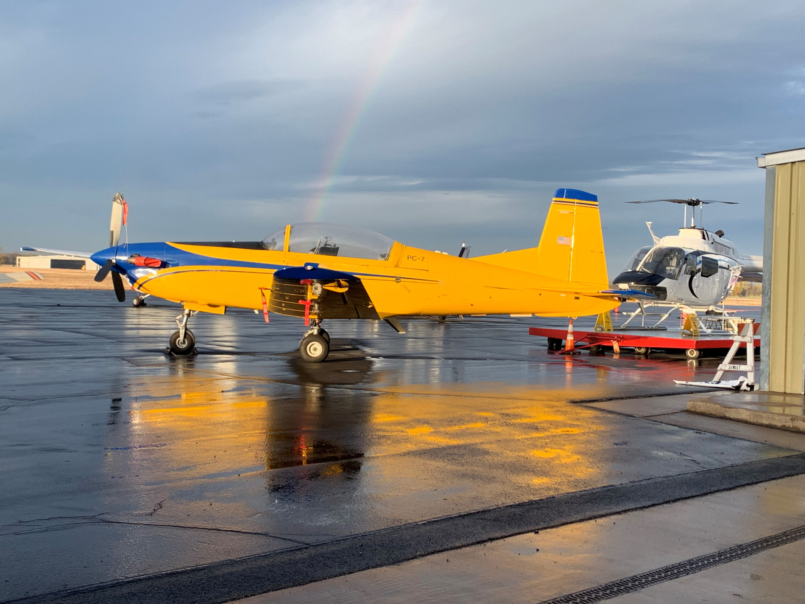
Moog’s Genesys Avionics Suite Selected for T-6A Avionics Program
Moog and Borsight Partner to Modernize U.S. Air Force Training Fleet Mineral Wells, TX – Moog Inc. (NYSE: MOG.A and MOG.B), a worldwide designer, manufacturer, and systems integrator of high-performance precision motion and fluid controls and control systems, announced today that its Genesys Avionics Suite™ has been selected for the U.S. Air Force T-6A […]
READ MORE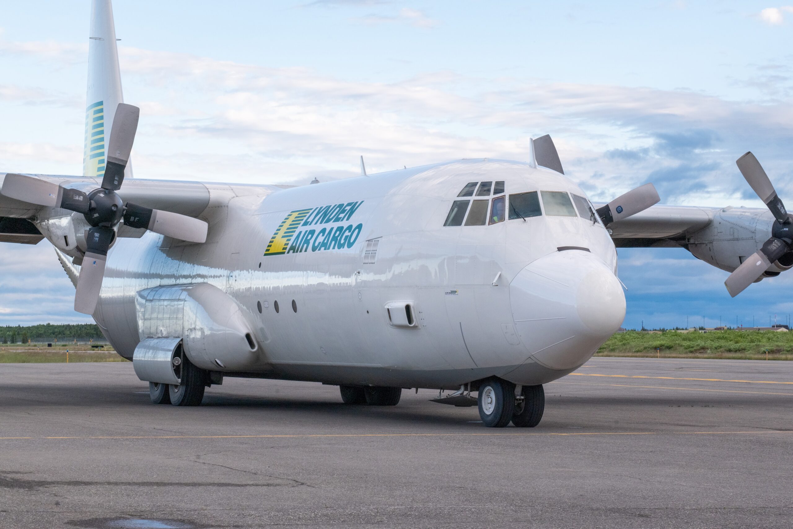
May 12, 2025
Moog Signs Lynden Air Cargo Hercules Fleet Upgrade Agreement
Contract Modernizes Fleet with Genesys Avionics Suite™ Mineral Wells, TX – Moog Inc. (MOG.A and MOG.B) announced that it has signed an agreement with Lynden Air Cargo to modernize its Lockheed Martin Model 382G Hercules fleet (L-382G) with the Genesys Avionics Suite™ to extend the operational life and improve mission effectiveness. The modernization effort […]
READ MORE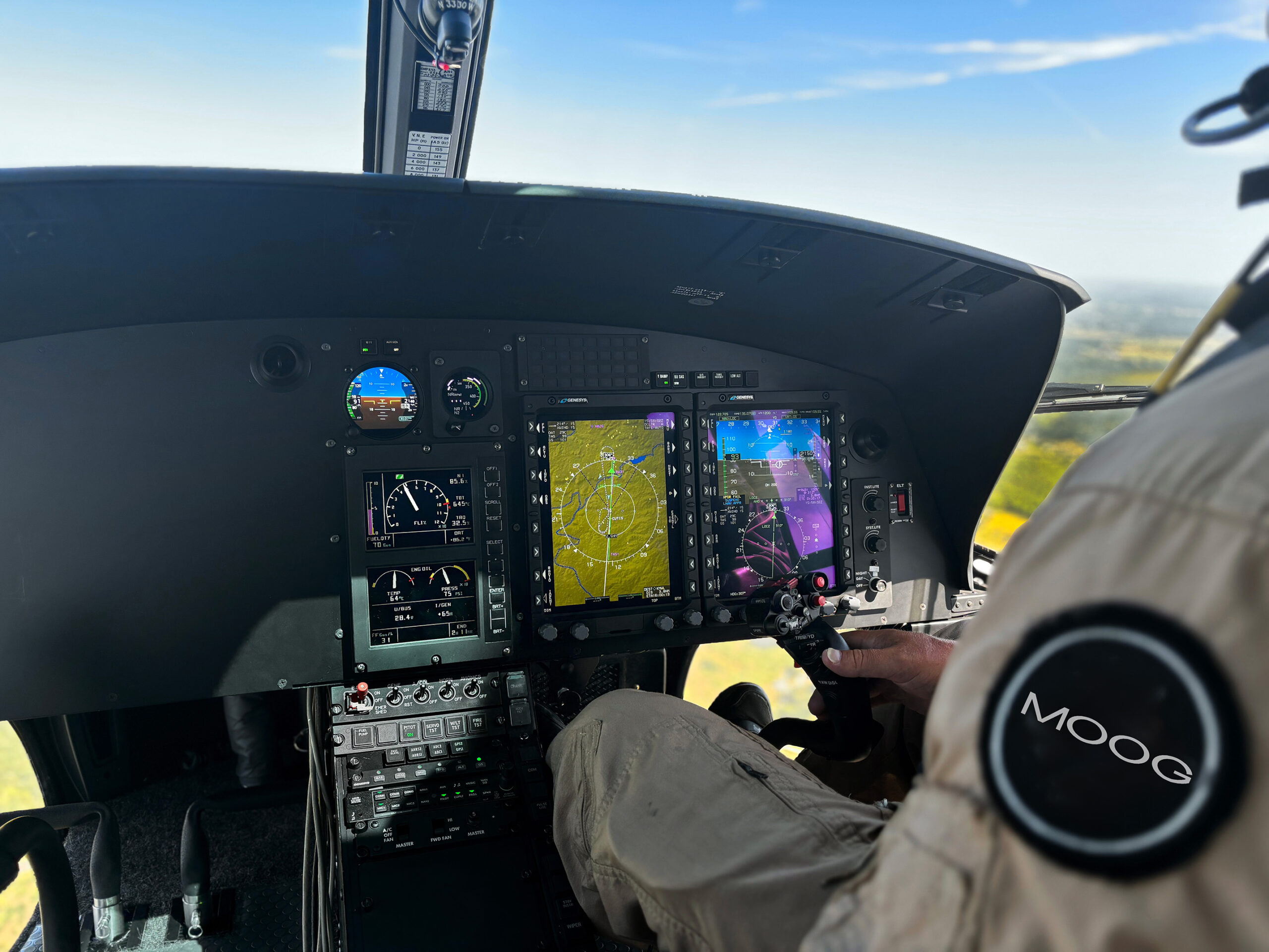
March 07, 2025
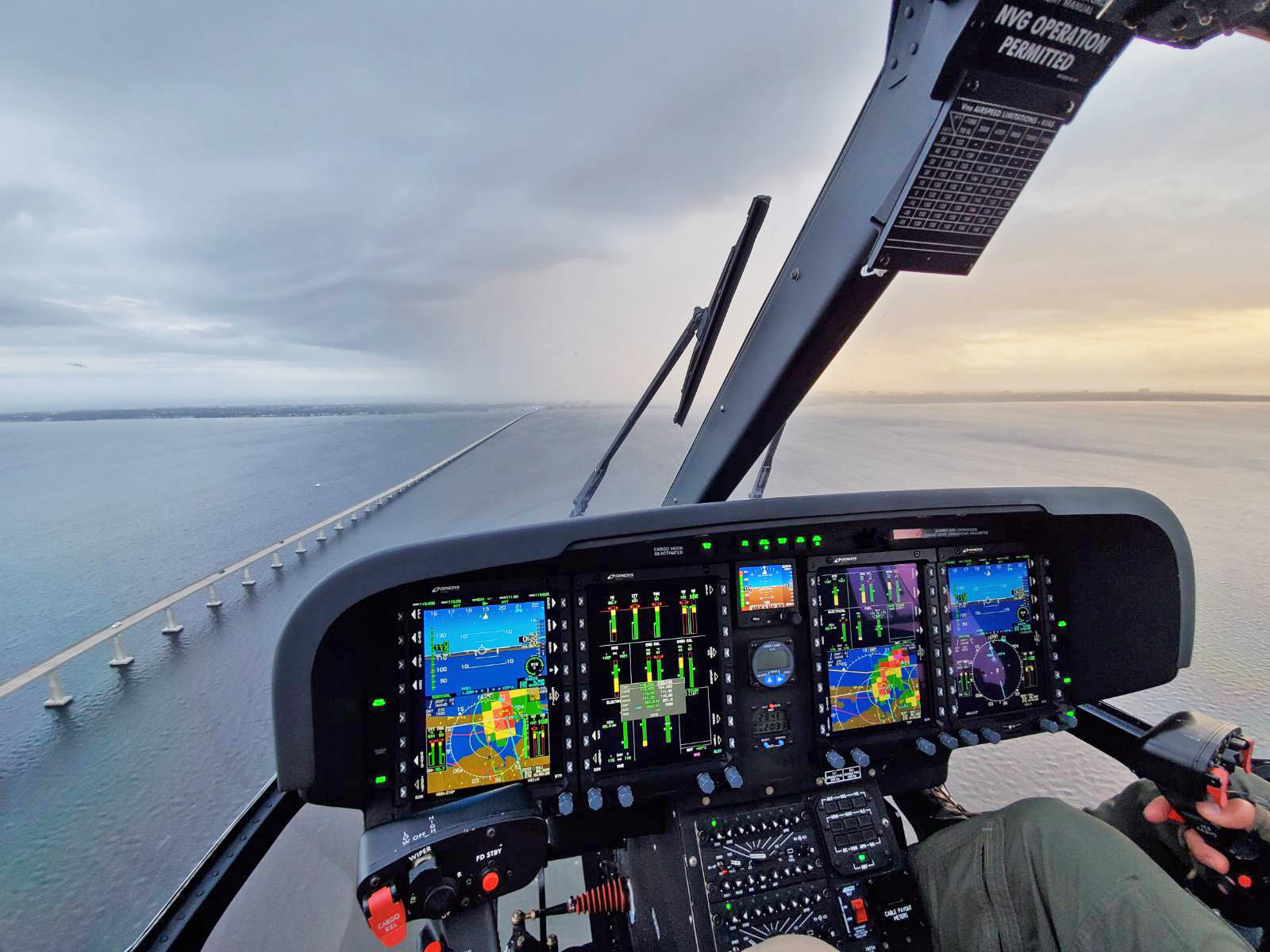
Airbus H125 IFR Cockpit Certified
Moog expands available solutions for single-pilot IFR operations on single-engine rotorcraft Mineral Wells, TX (March 7, 2025) – Moog announced that it has successfully received FAA Supplemental Type Certificate (STC) approval of its Genesys cockpit avionics suite for single pilot Instrument Flight Rules (IFR) operations on the Airbus H125 helicopter. The STC project was completed […]
READ MORE